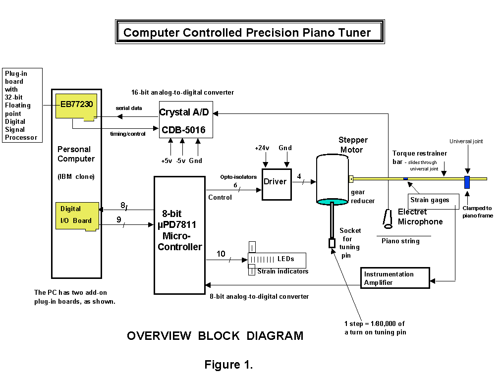
An IBM PC (clone) is used because of its availability, low cost, and wealth of support. The supervisory program is written in C. Two plug-in boards are used: 1) DSP evaluation board, and 2) digital I/O board. The supervisory program, operating in either manual or automatic mode, takes user commands via the PC keyboard, communicates on the PC bus with the two plug-in boards, and displays results from the two boards on the PC screen.
Data Acquisition
An electret
condenser microphone picks up the piano sounds and connects to an analog-to-digital
board containing a 16-bit A/D chip. The microphone signal is amplified
and anti-aliased filtered before its input to the A/D chip. Potentiometers
are used to control signal amplitude such that full A/D range is used without
clipping. Sampling frequency is about 12 KHz which is comfortably
more than twice the highest frequency of interest - about 4200 Hz.
The 16-bit sample word is clocked serially from the A/D chip into a serial
port on the DSP chip. The 16-bit fixed point word is easily converted
by software into the 32-bit floating point format used by the NEC DSP chip
(µPD77230).
µPD77230 DSP
Figure
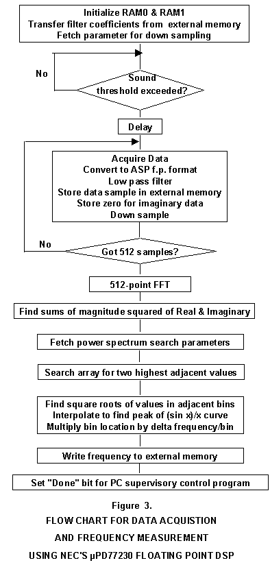
3 shows an overview flow chart of the various functions in the DSP program.
The chip has three types of memory on chip: 2K words of instruction
ROM, 1K of data ROM, and 2 blocks of data RAM, each 512 words. All
words are 32-bits wide. In addition, the chip can access external
memory containing instructions, data, or both. The two ROM
areas of this chip (mPD77230-003) are preprogrammed with many standard
DSP functions. The user program for this application executes in
external memory and calls the library subroutines in the Instruction ROM.
Library subroutines used in this application include data I/O, RAM initialization,
floating point division and square root, an FIR filter subroutine, and
512-point FFT (Fast Fourier Transform). In order to achieve fast
execution, filter coefficients are located in RAM0 while the acquired data
is stored in RAM1 (512 words each).
The external
memory on the EB77230 board is shared by the DSP chip and the PC, but only
one can access it at a time. When the user selects a note to be tuned,
the PC supervisor program downloads appropriate instruction code and filter
coefficients to the shared memory. On command, the supervisor relinquishes
control of memory and releases the DSP chip from reset - thereby
beginning a data acquisition and frequency measurement sequence.
After initialization, the program waits for the piano note to be struck.
When a level is exceeded (note struck), the program waits for about 400
milliseconds before collecting data samples. The initial percussive
effects, therefore, are not sampled.
In addition
to the shared memory, the EB77230 board has two 8-bit latches, each addressed
as the same memory location. One latch signals from DSP to PC; the
other, PC to DSP. The latches operate regardless of who has
control of the shared memory. Therefore, handshake signals
can flow either way at any time.
As mentioned above, the PC supervisor program downloads a file containing digital filter coefficients. The file selected is determined by the note being tuned. The coefficients are used by the DSP in a 512-tap FIR filter routine while logging sampled piano sound data. An appropriate low-pass filter allows only frequencies of interest to be logged for subsequent analysis. Why a 512-tap FIR filter? FIR filters are easy to work with, and the combination of the sampling frequency and DSP processor speed makes the rather long filter length feasible. Execution cycle time for the mPD77230 is 150 ns. For this application, the cycle time is adequate for nearly the full range of the piano. For the highest notes, a shorter filter is used because there is not enough time (1/11,894 = 84 us) between samples to compute an output value for every sample - using a 512-tap filter. (See down sampling discussion below.)
Digital filter coefficient files are derived off line using DISPRO filter design software package. Figure 4 shows three sample PC screens when using DISPRO.
Figure 4a. DISPRO Filter Parameter
Selection and Comparison Window
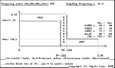
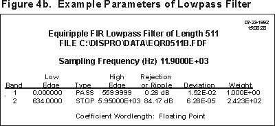
Figure 4c. DISPRO Display of Frequency
Response of Example of Lowpass Filter
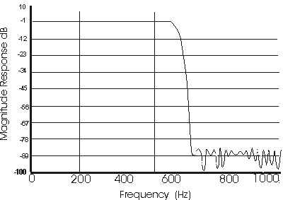
Figure 4a illustrates how
you can tweak the filter parameters to get desired properties. For
example, if you specify a sharper cutoff (transition from pass to stop
band), the length of the Parks-McClellan-Remez (PMR) FIR filter gets longer
- for a fixed sample rate. In this example, the cutoff and other
parameters were tweaked in order to get the 511 taps. Filter length
must be odd numbered. Any unused taps in the coefficient file generated
from DISPRO are zero filled. For example, if a 345-tap filter is
designed, the 512-345=167 remaining taps are zero filled. The performance
of the filter is unaffected by zero filling unused taps.
When
you accept the design parameters (shown in Fig. 4b.), DISPRO goes to work
and performs an iterative procedure involving millions of calculations.
Iterations continue until the output response is satisfied. (A math
coprocessor definitely helps!) Figure 4c is the frequency response
plot for the specified filter.
The
appended
paper on FFT bin interpolation states that a bandpass filter should
be used to pass only the frequency of interest. For example, even
the fundamental should be filtered out when measuring the second harmonic.
Experiments to-date, however, show no difference in measured frequencies
when using a lowpass versus a bandpass filter. Apparently the energies
of the two frequencies (fundamental and second harmonic) are far enough
apart so as not to affect one another. Lowpass filters cover a broader
range than bandpass, so fewer filters need be used.
Spectral analysis and FFT bin interpolation
After
sample data are acquired, filtered, and stored in RAM, the DSP program
performs an FFT and summation of the magnitude squared of real and imaginary
data. All imaginary data is zero filled. The program then searches
this summed data for the two adjoining bins (RAM locations) with the highest
values. Where to search in RAM is specified by parameters downloaded
from the PC supervisor.
Appended to this paper is another paper, FFT
Bin Interpolation, written by a good friend and former DSP colleague
at NEC, Barry Kulp. The conclusion from the paper is that, by interpolating
between the two highest adjoining values, the peak of the sin(x)/x curve
can be determined. The peak is the frequency of the piano note, either
its fundamental or second harmonic. The appended paper should be
studied before proceeding further with this discussion.
Down Sampling
Down
sampling is a means of increasing the resolution of the frequency spectrum.
With a sampling frequency of 11,894 Hz, together with down sampling,
the frequency spacing between bins of a 512 point FFT is as follows:
The lower the frequency of interest, then, the higher the Rd value. For example, when down sampling by 2, every other filter output sample is computed and stored for use later in the FFT. However, every sample acquired at the sampling frequency is stored in the tap delay buffer of the 512-tap FIR filter.Rd ft
Down FFT Approx.
Sampling Samp Cutoff fbin
Rate Freq* Freq Hz per bin ------------------------------------------
1 11894.0 5500 23.230469
2 5947.0 2800 11.615234
3 3964.7 1970 7.743490
4 2973.5 1450 5.807617
5 2378.5 1150 4.646094
6 1982.3 970 3.871745
7 1699.1 825 3.318638
8 1486.8 720 2.903809
9 1321.6 640 2.581163
10 1189.4 570 2.323047 ------------------------------------------
20 594.7 280 1.161523
-----------------------------------------
54 220.4 110 0.430194* also referred to as the "Fourier frequency"
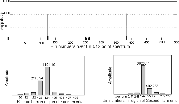
Figure 5. FFT Bin Interpolation
Magnitude Squared Power Spectrum When Measuring Frequency
of Middle C
| Terms defined:
Peak is the peak of the sinx/x shaped curved connecting the points of the power spectrum. First, find the highest two adjoining values in the magnitude squared power spectrum. The peak is usually between two points (or bins) of an FFT. Usually one bin's value is higher than the other. However, if two adjacent bins have the same value, the peak lies exactly between the two bin numbers. In the other unlikely extreme, if the values on either side of the highest value are equal, then the highest value is the peak of the superimposed sinx/x curve. L = square root of value in the lower location of the two bins; (lower of the two adjoining highest values). H = square root of value in the higher location of the two bins B = bin # of L D
= H/(L + H) = a fraction of fbin (see below)
fsamp = Sampling frequency Rd = down sampling rate "Fourier frequency" = fsamp/Rd fbin = frequency increment from one FFT bin to the next higher fbin = Fourier frequency/FFT size fpeak = Frequency at peak = (B + D ) • (fbin) |
Example calculation using Middle C
measurements:
FFT size = 512 points Fsamp = 11,894 Hz, Rd = 11 Fundamental:
Second Harmonic:
fpeak = (249.267)
• 2.112 = 526.418 Hz
Note that twice the fundamental
is
Due to inharmonicity, therefore, the actual second harmonic is 526.42 - 522.0 = 4.44 Hz higher than the theoretical second harmonic. This inharmonicity is the key factor in tuning a piano correctly. |
Frequency calculation
Figure
5 shows an example of the frequency calculation using real world data from
middle C on a piano. The topmost plot of RAM data (spectrum) shows
the symmetry of the lower 256 points with the upper 256. As mentioned
earlier, the supervisor program accesses table data consisting of previously
calculated parameters pertaining to the note being tuned. For tuning
middle C, the supervisor would write to the memory shared by the DSP program
a down sample rate of 11; further, it would tell where to start looking
in RAM for the fundamental and how many bins to search. Another parameter
would tell where to look for the second harmonic.
From
the human user's point of view, the display of the calculated frequency
is almost instantaneous after striking the piano key. Some of the
delay, of course, is intentional - in order to disregard the initial percussive
effects. As you might expect, the harder the piano key
is struck, the bigger the numbers in the power spectrum. It
is interesting to note also that, because the sound is sampled at a fixed
time delay after the key is struck, the frequency measured is higher for
a hard hit key than for a softer strike. The greater amplitude of
the vibrating string makes the string more taut during the brief time that
the sound is being sampled. This condition suggests the use of a
controlled blow for consistent precise measurements.
(Striking
the key with a good blow is important for getting equal tension in all
portions of the taut wire, e.g. on either side of the bridge.)
The subject
of inharmonicity appears throughout piano tuning literature. Observe
in Figure 5 that inharmonicity, in the measurement of middle C on the baby
grand piano used for this experiment, comes through "loud and clear".
(A large grand piano has less inharmonicity because the strings are longer
relative to diameter.)
Error calculation and response
This
being a closed loop control system, the supervisor must evaluate the sensor
input (measured frequency), compare the value with a set point (target
frequency), calculate a response, and send commands to adjust the system
(or plant) so as to reduce the error.
Consider
the case where a measured frequency is sharp compared with the target frequency.
As presently implemented, the system will start all over in order to tune
the note. That is, the tuning pin will be turned so as to flatten
the note below the target, and then approach the target asymptotically
from below. This, then, is an over-damped control system where it is important
not to overshoot the target. Piano tuners usually work the other
way; that is, they tune a note slightly sharp and then back off slightly.
Experience may indicate that the CCPPT should use the same procedure.
If so, a small software change in the supervisor program is required.
Data
was obtained in manual mode in order to derive steps-per-hertz response.
In the vicinity of middle C, frequencies were recorded after 50-step increments.
A plot of the data shows a pretty linear response of about 87 steps per
hertz.
In our
example, where the note measures 260.988 Hz, the calculated response is
87 x (261.626 - 260.638) or 55 steps in the sharp direction. Since
it is important not to overshoot, something less 55 steps will commanded
to the stepper motor. The process of measuring and responding is
repeated until the error is tolerably small. In this region of the
piano, 0.638 Hz error is not acceptable. A beat period of 1/0.638
(about 1.5 seconds) is readily detected.
Piano
tuners use the term "cents" to describe the amount of error. A "cent"
is 1/100th of a 1/2 step interval. In this case, the half-step interval
from C-4 to C#-4 is 15.6 Hz, so one cent is 0.156 Hz. Our Fig. 5
example note is about 4 cents flat. Table data is also referenced
by the Supervisor to judge when the error is below a maximum value.
When this point is reached, the note is tuned. Arbitrarily, the maximum
error is set at one Cent.
Non-linear response
As seen
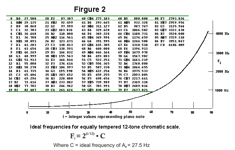
in Figure 2, the half step interval from C1 to C#1 is only about 1.9 Hz,
whereas from C7 to C#7, the difference is about 124 Hz. In the first
example, one cent is 0.019 Hz; in the second example, 1.24 Hz. The
response calculation must account for this non-linearity. Steps-per-Hertz
data was derived experimentally from various regions of the piano, and
a curve fitted to the compiled data. The curve looks like the mirror
image of Figure 2. For example, for the lowest notes, about 1600
steps are required to raise the frequency by one Hertz, whereas near the
top, only 4 steps are required. The change in Steps-per-Cent is much
less: about 40 Steps/Cent for low notes, about 7 Steps/Cent for high
notes.
High
notes fade much faster than low notes, so beats are much harder to hear.
High notes, then, are more difficult to tune manually than low notes.
CCPPT doesn't care which region is being tuned because the algorithm is
not concerned with beats.
Different
size pianos have different length strings. The bigger the piano,
the higher the number of Steps-per-Hertz. The referenced look-up
table data is just a starting point. After the system is fully tensioned
(see next section), the Supervisor can gather its own Steps-per-Hertz data
for the particular piano being tuned. The response calculation is
adjusted accordingly.
System stress/strain monitoring
Up to
this point, mechanical issues have not been discussed. But they can't
be ignored! Starting with a slip-fitting socket that engages the
tuning pin, through gearing and motor, and on through linkage in the torque
restraining bar to the clamp secured to the piano frame (see Figure 1),
there are many sources of backlash. The system supervisor, therefore,
needs to know when the motor is stepping against a torque load or is just
turning to take up mechanical slop in the system. In order to monitor
system strain, two strain gages are mounted on flat spots in the middle
of the torque restrainer bar. The electrical resistance of a strain
gage varies with strain. The two strain gages in the CCPPT form the
variable resistances in a bridge circuit. The voltage output from
the circuit is amplified and input to an 8-bit A/D converter which is incorporated
in the micro-controller chip (µPD7811) which controls the stepper
motor. (This A/D converter has nothing to do with the A/D converter
for the audio signal.) The A/D reading is passed back to the supervisor
as part of its routine data exchange when a move has been completed.
One of the coded commands from the PC to the motor controller is simply:
step in the sharp direction until the strain gage reading = x value.
In order to aid the tuning process while in Manual mode, the strain gage
reading is converted to one of eight levels, and the resulting value is
output to 8 LEDs. One of two additional LEDs indicates the direction
of the strain. The vector is also displayed on the PC screen.
Stepper motor control
When
the commanded number of steps is received by the µPD7811 from the
PC supervisor, the number is read by a timer interrupt service as a counter.
The interrupt service increments or decrements (depending on commanded
direction) through a table of stepper motor output patterns. Four
wires connect to poles in the stepper motor; a pattern consists of some
pair being turned on while the other pair is off. The counter is
decremented with each change in output pattern - until the counter is zero;
job done.
Piano tuner's skepticism
When
demonstrating the CCPPT at a Piano Technicians Guild convention (April
1992), the most common observation/criticism by the professionals focused
on the actual turning of the tuning pin. Many tuners feel that manipulating
the "hammer" (wrench) is the real art in tuning a piano so that it stays
tuned. (No piano does, but it's all relative!) Only experience
will vindicate or dispel the professional tuner's skepticism. However,
tuners are likely to underestimate the power, flexibility, and repeatability
of digital control!
One action
which the CCPPT does not do but which human tuners cannot help doing is
bending the tuning pin; not literally bending it, but leaning perpendicular
to the axis of the pin in order to back off ever so slightly. Over
a period of many tunings, bending the pin will cause it to loosen in the
wooden pin block.
Improving precision in frequency measurement
In selecting
components for the CCPPT prototype, high precision was a priority.
There are, however, a number of steps which can yield still more precision
if experience indicates a need. A 16-bit A/D converter is quite standard,
but more precise (e.g. 18-bit) converters than the one used here
are available. As for FFT's, every doubling in size reduces the distance
between bins by half. NEC has just published an 8K-point FFT application
note. This is 16 times bigger than the 512-point FFT used here.
Using the 8K FFT, the interpolation process, then, would be 16 times more
precise. If the 8K FFT calculation were deemed too slow (it is much
less than 1 second), then a faster DSP chip is available from NEC (µPD77240).
A higher
sampling frequency would allow more precise down sampling, particularly
for measuring the high notes. The "Fourier frequency" (see Appendix)
could then be closer to exactly four times the frequency of interest.
As mentioned
above, the algorithm used here does not use beats for setting temperament;
that is, setting the intervals in the middle octave. If such a procedure
were desired, then frequencies of harmonics other than second harmonic
could be measured, stored, and referenced for calculating a beat frequency
of interest - for example in setting the major sixth or major third intervals,
e.g. C4 to A4 or C4 to E4 respectively. (No interval is beatless
in a 12-tone tempered scale.)
Conclusion
Digital
Signal Processing opens the door for economical and precise analysis and
measurement of piano sounds. A closed-loop digital servo loop using
an electric motor provides a method of turning the piano's tuning pins
in a precise repeatable manner.
Click to view picture taken at Piano Technicians Guild Regional Seminar.
Click to view a later revision to the hardware implementation.
Click to view a video of a hand operated version. No motor used.
Acknowledgments:
|
|
