|
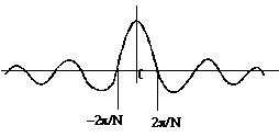
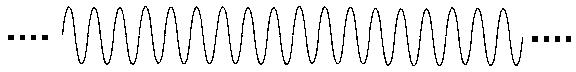
COMPUTER CONTROLLED PRECISION PIANO TUNER FFT BIN INTERPOLATION When using FFTs for frequency measurement, greater resolution requires longer sample windows. For example, if the sample window is one second long, the FFT bin center frequencies* are spaced at 1 Hz intervals. To get bin center frequencies at 1/2 Hz intervals, the sample window must be 2 seconds long. For the piano tuner, it is necessary to measure frequency with precision finer than 1/6 Hz, but with sample windows much shorter than six seconds. Therefore, some method for interpolating frequency measurements between FFT bins must be used. When calculating an FFT on a long sequence of data points (longer than the length of the FFT), the sequence must be windowed with a multiplying function that is only non-zero within the scope of the FFT. For example, a pure sine wave extends from - ¥ =< to =< ¥, as shown in Figure 1. An FFT covers a finite number of points, so multiply the sine wave (Fig. 1.) by the window, as in the example windows shown in Figures 2a and 2b. *Bin center frequency is the frequency at each point in an FFT. For example, if a 512 point FFT is performed on a band width of 5 KHz, the bin center frequencies will be separated by 5000 / 512 = 9.766 Hz = fbin. The bin frequencies will be 0, fbin, 2fbin, 3fbin, 4fbin, ... . |
| Figure A1. Continuous Sine
Wave
|
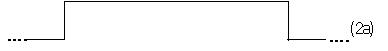
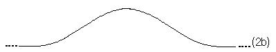
| Figures 2a & 2b: Two examples
of Windows
Rectangular Raised Cosine |
|
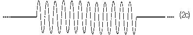
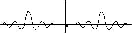
Figure 2c shows the windowed output from a rectangular window.
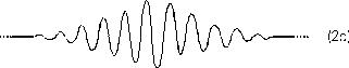
Figure 2d is the output from a raised
cosine window.
|
| Recall that multiplication in the time domain is equivalent to convolution in the frequency domain. Therefore, the nice pure spectrum of the sine wave in Figure 3a has been blurred by the spectrum of the window, Figure 3b, to give the result in Figure 3c. |
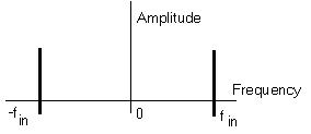
Figure 3b Spectrum of the window
Figure 3c Blurred signal
|
| The rectangular window is
the simplest one to implement since it consists of just truncating the
infinitely long input sequence to the number of points in the FFT operation;
and the signal samples require no multiplication operations. Therefore,
we will use the rectangular window function for this application.
We know that the blurring function of the rectangular window (Fig. 3b) is: sin (w/2) sin(k2p/N N/2) = sin kp = 0 Therefore, we can conclude that a sine wave with a frequency that is exactly on a bin center frequency of an N-point FFT will produce an FFT that has no leakage into other bins, since that is where the zeroes of the blurring curve lie. The bin centers fs - 2p/N, fs, fs + 2p/N would correspond to -2p/N, 0, 2p/N in the "blurring function" above. We know, too, that fs is somewhere between the two bins with the greatest energy in them. This seems obvious from a graphical inspection, until you ask, "what if fs is very near bin M, so bin M+1 has a very low value. Couldn't bin M-1 have more than M+1 (assume fs > M)?" The answer is no. The numerators, sin (w N/2), where w = fs-(M-1), fs-(M+1), would be equal in magnitude by the symmetry of the sine function, but the denominator, sin(w /2), would be smaller the closer you are to fs; therefore bin M+1 has a greater value. However, what happens when the input frequency, fs, does not exactly match a bin center frequency? Essentially, the FFT is sampling the frequency response (or spectrum) of the signal, so we look at it as in Figure 4. Figure A4. Frequency Response when Input Frequency does not match FFT Bin Center Frequency 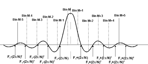 The response in any given
bin is a function of the distance from the input frequency to the bin center.
where M, M+1, are multiples of 2p/N, fs is (M + 0.D) 2p/N. So, the numerators above become: sin((0.D) (2p/N) (N/2)) and sin((0.D - 1) (2p/N) (N/2)) which reduce to:
which, by symmetry of the sine wave, have equal magnitudes. Therefore, the ratio of the bin values is equal to the ratio of the denominators: 
by magnitude symmetry of sine wave However, sin x
» x when x is small, with
the worst case deviation occurring where 0.D
or 1 - 0.D
is near 1. If N is large, x is automatically very small. For
example, if N = 128, how good an approximation is
Therefore,  Therefore, knowing the magnitudes of the two largest FFT bin results, we can solve for 0.D and therefore, fs. This procedure would work perfectly for a pure complex sinusoid. Any other signals present would also contribute some side lobe energy to the bins of interest - thereby corrupting the calculations. Even a real sinusoid has both a "positive" and "negative" frequency component. If the input signal is known to be, or can be filtered to be, a "clean" sine wave, the side lobe energy from the "negative" frequency component can be made negligible by making it be "far away", which is optimized when fs = (fsamp)/4 Also, increasing N will minimize the "other" side lobe energy. This ratio, then, is a satisfyingly simple approach to interpolating frequency measurements between FFT bins for signals having the restrictions noted above regarding other frequencies present. In the context of the piano tuner, this procedure may be used to provide fast, precise frequency measurements of either the fundamental or second harmonic of the struck note. For optimum performance, the only other digital signal processing required is to bandpass filter (allowing only signals in the region around the frequency of interest to pass through) and decimate the filter result so that the sampling frequency is approximately four times the frequency of interest. Barry D. Kulp
|